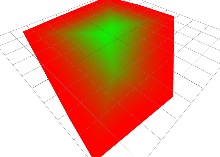
There are two options for edge detection, either doing a full screen postprocessing pass and then a novel approach for detecting edges using a concave hull algorithm.
Postprocessing Pass
Sobel edge
You may or may not of heard of sobel edge detection. This is one technique used with postprocessing to detect the edges of the entire scene.
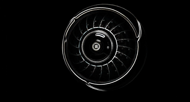
This technique is a screen effect, meaning it is applied to everything. You could use layers and render just a subset of the scene and merge in a merge pass.
This has its uses in certain circumstances when you trying to affect more than one item in a scene.
Depth Pass
Depth passes are very useful when trying to do edge detection. Take the scene below for example (from codesandbox by Mugen87)
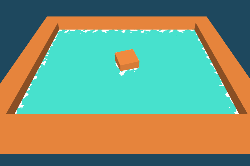
This has the advantage of being focused specifically around the difference in depth between two layers.
I.e. one layer will do a depth pass on water plane and another on the surrounding cuboids in this case. Then a comparison is made using the same fragments and potentially differing depth values ranging from floats 0-1.
You use the same set of uvs and sample each depth pass texture at the same fragment, if the difference between depths is > 0.01 or some scalar or constant. Then you render foam on the water plane.
This is a neat solution but not ideal when you have large scenes and multiple postprocessing effects and this takes 2 renders of the scene.
Welcome a 3rd option..
Concave Hull Edge Detection
What is a concave hull? An image speaks a thousand words:
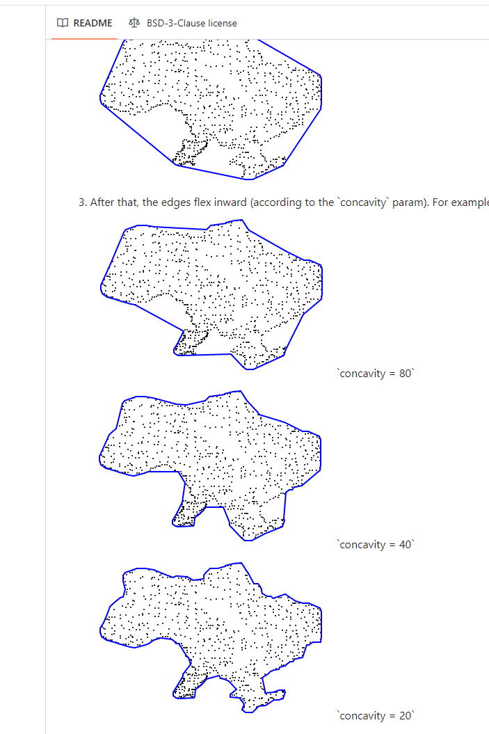
It essentially is a mathmatical algorithm which provides the edges of a given mesh or hull.
The technique works with 2D planes, i.e. on the x/z axis. Or atleast I havent tried adding a third dimension.
But so what if we have the edges in the JS Three app?
Well we can now pass these edges to the shader. Once in the shader we can find the closest edge and color accordingly (I say accordingly but it’s not so obvious how to accomplish this - to be exampled below). Obtaining something like this:
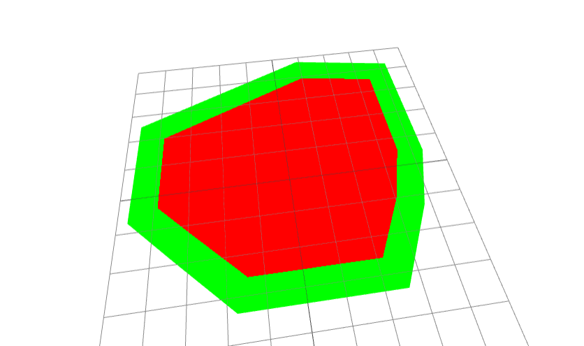
The shader code is here:
1uniform vec2 lines[_LINEPOINTS_];2varying vec3 vPosition;34float distanceToSegment(vec2 p, vec2 a, vec2 b) {5 vec2 ba = b - a;6 vec2 pa = p - a;7 float h = clamp(dot(pa, ba) / dot(ba, ba), 0.0, 1.0);8 return length(pa - ba * h);9}1011void main() {12 // Stepper params13 float minDistance = 3.0;14 float contourThickness = 40.0;1516 // gradient params17 // float minDistance = 1.0;18 // float contourThickness = 4.0;1920 for (int i = 0; i < int(_LINEPOINTS_); i++) {21 vec2 a = vPosition.xy;22 vec2 b = lines[i].xy;23 vec2 c = lines[(i + 1) % int(_LINEPOINTS_)].xy; // Wrap around for the last segment24 float distance = distanceToSegment(a, b, c);25 minDistance = min(minDistance, distance / contourThickness);26 }2728 float stepper = step(minDistance, 0.02);2930 gl_FragColor.rgba = mix(31 vec4(1.0, 0.0, 0.0, 1.0),32 vec4(0.0, 1.0, 0.0, 1.0),33 // smoothstep(0.0, 1.11, minDistance)34 stepper35 );36}
First things first, the uniform has the format of this:
1uniform vec2 lines[_LINEPOINTS_];
Now if you left it like this and didn’t modify the definition of the shader, it would give you a compiler error as LINEPOINTS is not defined yet and wont be, its just a placeholder to do a replaceAll on. Remember when we create the shader its just a string, allowing us to use all the string methods we have in JS if we so please.
What we need to do is this:
1<mesh rotation={[-Math.PI / 2, 0, 0]}>2 <shapeGeometry args={[shape, 8]} />3 <shaderMaterial4 uniforms={uniforms}5 vertexShader={vertexShader}6 fragmentShader={fragmentShader.replaceAll("_LINEPOINTS_", edges.length)}7 />8</mesh>
Im not going into how to collate the edges, you can take a look at the codesandbox. But essentially using this library via npm.
The actual colouring is done of a distance variable from the edges given a fragment position. Pass as a varying to the fragment shader.
1float distanceToSegment(vec2 p, vec2 a, vec2 b) {2 vec2 ba = b - a;3 vec2 pa = p - a;4 float h = clamp(dot(pa, ba) / dot(ba, ba), 0.0, 1.0);5 return length(pa - ba * h);6}78//........910for (int i = 0; i < int(_LINEPOINTS_); i++) {11 vec2 a = vPosition.xy;12 vec2 b = lines[i].xy;13 vec2 c = lines[(i + 1) % int(_LINEPOINTS_)].xy; // Wrap around for the last segment14 float distance = distanceToSegment(a, b, c);15 minDistance = min(minDistance, distance / contourThickness);16}
This looks complicated but the idea is that, you loop through each pair of edge vertices and given we have looped through all the pairs, which line or pair of vertices is closest to out vPosition for this fragment?
Once we have this minDistance we can use to colour the shape:
1float stepper = step(minDistance, 0.02);23gl_FragColor.rgba = mix(4 vec4(1.0, 0.0, 0.0, 1.0),5 vec4(0.0, 1.0, 0.0, 1.0),6 // smoothstep(0.0, 1.11, minDistance)7 stepper8);
Steppers are a cut off (I played around with this alot) but essentially if the given value (minDistance) is above 0.02 then we get 1.0 as the value for stepper and if below then we get 0.0.
1float stepper = 0.02===3gl_FragColor.rgba = vec4(1.0, 0.0, 0.0, 1.0)4===5red67or second option...89float stepper = 1.010===11gl_FragColor.rgba = vec4(0.0, 1.0, 0.0, 1.0)12===13green
This gives a very clear boundary.
If you comment out the stepper in the gl_FragColor and uncomment the smoothstep and the gradient params, then you can obtain a gradient going from the center to the edges. Not perfect but still accomplishes edge detection with gradients 🙏 i.e.
