For a long time I wondered if it were possible to store positional XYZ vectors inside the rgba channels of an image. And it is possible!
The workflow involves using blender, sverchok and r3f in a codesandbox.
The approach will be:
- Distribute points on a plane using geometry nodes
- Using sverchok extract positional data of points
- Map the vector components X/Y/Z into range 0-1 appropriate for images
- Store position data into an image via a blender api script
- R3F setup and using these positions in an image
- How to check we have the right data in the image/texture
Intro
Here is the over all setup for sverchok nodes:
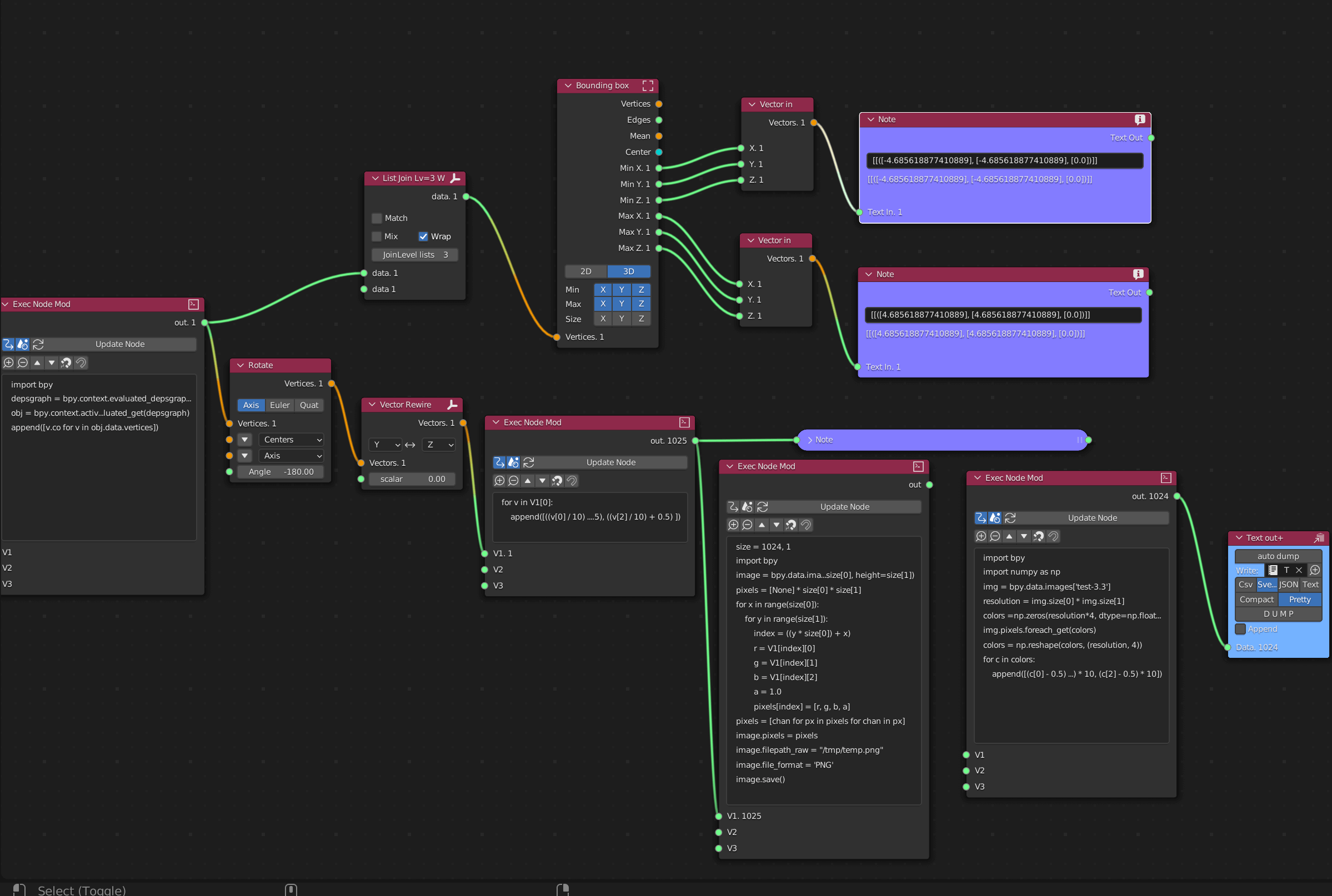
I did it using this as its my new favourite toy but also allows you to break things down instead of one big scary python script file. Plus I find node based work flows easier than using entirely the blender python api…
Distribute points on a plane using geometry nodes
Im not going to go into great detail on this as you can view a previous article here.
The thing here is we need to distribute points on a mesh and ensure there are enough data points to fill a texture. Not essential though.
Any queries or issues contact me via my email [email protected]. Always happy to help and teach what I know.
Using sverchok extract positional data of points
Here is the overall sverchok node setup:

And this is the script we use to extract the vertex position data of the points spread on the plane:
1import bpy23depsgraph = bpy.context.evaluated_depsgraph_get()45obj = bpy.context.active_object.evaluated_get(depsgraph)67append([v.co for v in obj.data.vertices])
Nope I havent just learned python over the past 2 weeks 😆 lots of googling and playing around to find out what works!
This will extract all the positional info we need to be able to store in a image/texture.
The next bit or rotating and rewiring the y and z values I dont think we particularly need. As rotating on the buffergeometry in r3f seems to work just fine.
Map the vector components X/Y/Z into range 0-1 appropriate for images
The next bit is they key bit, which im not a 100% sure on the whys. I have a fair idea why, but yea, we need to store positional values in 0-1 range for rgb data.
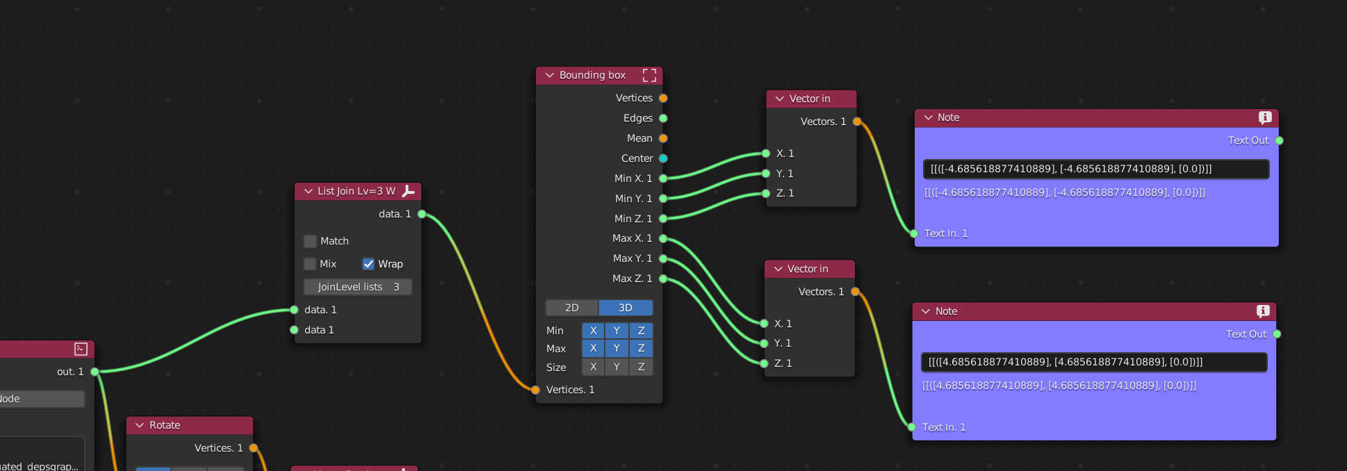
So we need to know the max and min ranges of the +/- axis ie the size of the bounding box of all coordinates in our scene (for simplicity I chose to do a plane for this initial test).
These nodes give us the min max values:
Im alittle unclear on color management and formats so far and definately not an expert. But you need to be careful your data is stored linearly, i.e. isnt manipulated into some kind of sRGB or amended via gama correction, and in addition we dont want any kind of compression as this will affect the precision of the floats we are going to store.
So why is this important? textures like PNGS as far as I know (well not 100% sure on exr files) need to store data in 0-1 as previously stated, imagine our scene expands -5 to +5 on all axis’s so we map it by doing:
1/*2x values for example3const r = (value / total range) + 0.54const x = (value - 0.5) * total range */5const xCoord = -56const redValue = (-5 / 10) + 0.57= -0.5 + 0.58=0910// Convert back to coordinate again11const xValue = (0 - 0.5) * 1012=-0.5 * 1013=-5
As you can see the values map to and from rgb to xyz and back again.
Nice aint it :) similiar to how you would map coordinates in glsl shaders from -1 to +1, to 0 to +1 for coordinate systems.
So we now have a way of mapping coordinates to fit in rgb channels.
Store position data into an image via a blender api script
We have two options really we either bake a texture via mapping the rgb mapped data to a plane geometry or we do what I have done and save an image via a python api script.
Here is the script for saving the image, before doing this, be sure to disable these two buttons, we dont want it to save on change, wayyy too many images haha:
(do not have these enabled)

and here is the script:
1size = 1024, 12import bpy3image = bpy.data.images.new("test-3.3", width=size[0], height=size[1])4pixels = [None] * size[0] * size[1]5for x in range(size[0]):6 for y in range(size[1]):7 index = ((y * size[0]) + x)8 r = V1[index][0]9 g = V1[index][1]10 b = V1[index][2]11 a = 1.012 pixels[index] = [r, g, b, a]13pixels = [chan for px in pixels for chan in px]14image.pixels = pixels15image.filepath_raw = "/tmp/temp.png"16image.file_format = 'PNG'17image.save()
Essentially we create an image we have a V1 which is the vertex data input about the points positions.
A key thing here is that the number of distributed points on the plane has to match up, as we map through the range of pixels 1024 to 1 (the image) and 1024 data points.
The thing is so long as the total number of texture pixels is <= to the data points this will work, otherwise the range below will try and access V1 (the data) and will be out of range…
1for x in range(size[0]):2 for y in range(size[1]):3 index = ((y * size[0]) + x)4 r = V1[index][0]5 g = V1[index][1]6 b = V1[index][2]
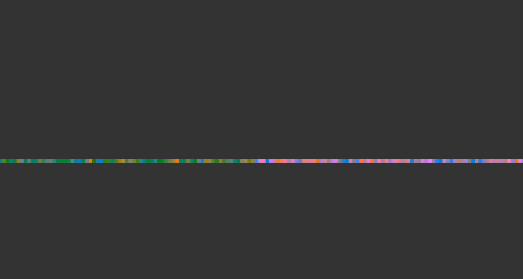
To view the image we can just click the update node and open up an image editor tab.
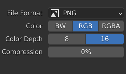
One thing to note at this point is that when you save as the image we want zero compression, save as rgb and 16 bit.
R3F setup and using these positions in an image
Here is the codesandbox:
and here is the blender file for you to play around with:
This is the main file:
1import "./styles.css";2import { Suspense, useRef, useEffect } from "react";3import { Canvas, useLoader } from "@react-three/fiber";4import { OrbitControls } from "@react-three/drei";5import download from "./orb.png";6import * as THREE from "three";7import { useMemo } from "react";8import texture from "./test-3.3.png";910function Points() {11 const tex = useLoader(THREE.TextureLoader, texture);12 tex.encoding = THREE.LinearEncoding;13 const orb = useLoader(THREE.TextureLoader, download);14 const pointsRef = useRef();1516 const shader = {17 uniforms: {18 positions: {19 value: tex20 },21 orb: {22 value: orb23 }24 },25 vertexShader: `26 uniform sampler2D positions;27 attribute float index;2829 void main () {30 vec2 myIndex = vec2((index + 0.5)/1024.,1.0);3132 vec4 pos = texture2D( positions, myIndex);3334 float x = (pos.x - 0.5) * 10.0;35 float y = (pos.y - 0.5) * 10.0;36 float z = (pos.z - 0.5) * 10.0;3738 gl_PointSize = 10.0;39 gl_Position = projectionMatrix * modelViewMatrix * vec4(x,y,z, 1.0);40 }41 `,42 fragmentShader: `43 uniform sampler2D orb;4445 void main () {46 float alpha = texture2D(orb, gl_PointCoord.xy).a;47 //If transparent, don't draw48 if (alpha < 0.005) discard;4950 vec4 color = texture2D(orb, gl_PointCoord.xy);51 gl_FragColor = color;52 }53 `54 };5556 let [positions, indexs] = useMemo(() => {57 let positions = [...Array(3072).fill(0)];58 let index = [...Array(1024).keys()];5960 return [new Float32Array(positions), new Float32Array(index)]; //merupakan array yang sesuai dengan buffer61 }, []);6263 return (64 <points ref={pointsRef}>65 <bufferGeometry attach="geometry" rotateX={Math.PI / 2}>66 <bufferAttribute67 attach="attributes-position"68 array={positions}69 count={positions.length / 3}70 itemSize={3}71 />72 <bufferAttribute73 attach="attributes-index"74 array={indexs}75 count={indexs.length}76 itemSize={1}77 />78 </bufferGeometry>79 <shaderMaterial80 attach="material"81 vertexShader={shader.vertexShader}82 fragmentShader={shader.fragmentShader}83 uniforms={shader.uniforms}84 />85 </points>86 );87}8889function AnimationCanvas() {90 return (91 <Canvas camera={{ position: [10, 10, 0], fov: 75 }}>92 <OrbitControls />93 <gridHelper />94 <Suspense fallback={"hello"}>95 <Points />96 </Suspense>97 </Canvas>98 );99}100101export default function App() {102 return (103 <div className="App">104 <Suspense fallback={<div>Loading...</div>}>105 <AnimationCanvas />106 <gridHelper />107 </Suspense>108 </div>109 );110}
A few key things here, we use points with a buffergeometry and set attributes which will be available per vertex on each vertex shader run.
We have to have both an array of positions x/y/z, 3072 length (3 seperate components per vertex) and a index used to read the texture, length 1024 (1 component per vertex). Here is how we read the rgb value and convert to a position in the vertex shader:
1vec2 myIndex = vec2((index + 0.5)/1024.,1.0);23vec4 pos = texture2D( positions, myIndex);45float x = (pos.x - 0.5) * 10.0;6float y = (pos.y - 0.5) * 10.0;7float z = (pos.z - 0.5) * 10.0;
So the myIndex is the index + 0.5 (to center it) and then /1024 as this is the size of the texture we created in blender with the positions in.. getting the uv’s in the range 0-1 which is what we need.
We sample the texture and then do the conversion. The conversion could be simplified in glsl but for simplicity and to make it easier to follow I did it per component of the vector! 🙂
And then all we have to do is the usual in the vertex shader:
1gl_PointSize = 10.0;2gl_Position = projectionMatrix * modelViewMatrix * vec4(x,y,z, 1.0);
Plus dont forget blender is X up and three/r3f is y up. So we need to rotate the buffer geometry:
1// rotateX2<bufferGeometry attach="geometry" rotateX={Math.PI / 2}>3 <bufferAttribute4 attach="attributes-position"5 array={positions}6 count={positions.length / 3}7 itemSize={3}8 />9 <bufferAttribute10 attach="attributes-index"11 array={indexs}12 count={indexs.length}13 itemSize={1}14 />15</bufferGeometry>
How to check we have the right data in the image/texture
So how can we check that we have the right data in the image and precision isnt too off.
Well first off the evaluated tab on geometry nodes superficially rounds up so I dont think we can check this way.
What we can do is out put the data when we grab the vertex data and then use this final bit of the node setup to read the pixels and convert back:
These are the two bits of sverchok nodes we are insterested in:
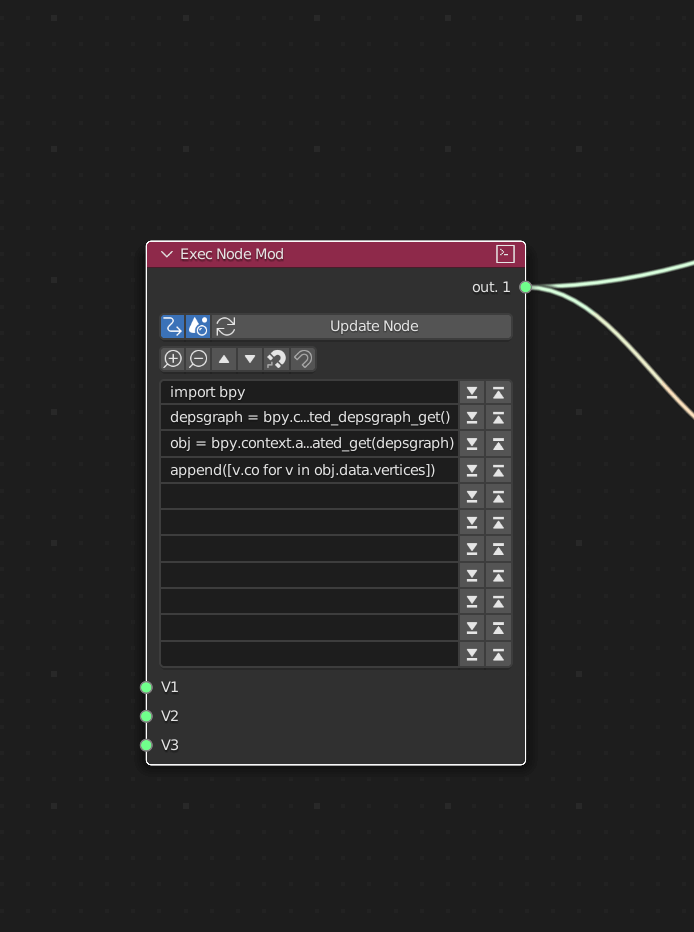
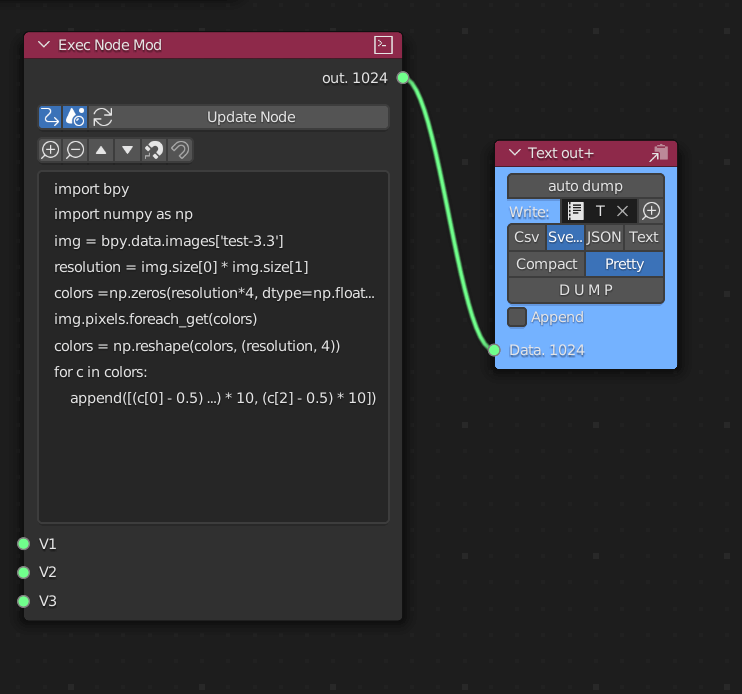
The script for reading back color pixels from an image is here:
1import bpy2import numpy as np3img = bpy.data.images['test-3.3']4resolution = img.size[0] * img.size[1]5colors =np.zeros(resolution*4, dtype=np.float32)6img.pixels.foreach_get(colors)7colors = np.reshape(colors, (resolution, 4))8for c in colors:9 append([(c[0] - 0.5) * 10, (c[1] - 0.5) * 10, (c[2] - 0.5) * 10])
This will read pixels and append the converted data to xyz to an text out node, making sure sverchok and pretty are selected on this text out node.
Here is array of data from the image texture:
1[2 [4.686275124549866, 0.019608139991760254, -4.686274491250515],3 [-4.686274491250515, 0.019608139991760254, -4.686274491250515],4 [4.686275124549866, -0.0196075439453125, 4.686275124549866],5 [-4.686274491250515, -0.0196075439453125, 4.686275124549866],6 [-0.6862741708755493, 0.019608139991760254, -1.823529303073883],7 [-3.235294073820114, -0.0196075439453125, 2.9607850313186646],8 [-4.176470562815666, 0.019608139991760254, 1.0392159223556519],9 [-0.09803891181945801, 0.019608139991760254, -1.5882351994514465],10 [-1.2745097279548645, 0.019608139991760254, -0.0196075439453125],11 [-0.0196075439453125, 0.019608139991760254, -3.7843136489391327]12]
and here is the array of data from just grabbing the vertex data: (the first script node we ran to grab position data)
1[2 [4.685618877410889, 4.685618877410889, 0.0],3 [-4.685618877410889, 4.685618877410889, 0.0],4 [4.685618877410889, -4.685618877410889, 0.0],5 [-4.685618877410889, -4.685618877410889, 0.0],6 [-0.6909056901931763, 1.8132230043411255, 0.0],7 [-3.253396511077881, -2.947563648223877, 0.0],8 [-4.18233060836792, -1.0568175315856934, 0.0],9 [-0.11107802391052246, 1.5750043392181396, 0.0],10 [-1.25852632522583, 0.021483659744262695, 0.0],11 [-0.006344318389892578, 3.7792344093322754, 0.0]12]
As you can see some detail/precision is lost and I am working on this, I think saving as a 32 bit floating point number will help this. And also I think color management also has played a part in this precision error.
Final Thoughts
For general partciel simulations this will work quite nicely, or for another way to instance something and use the opacity mask / discard.
In general quite happy with how this turned out, many many attempts were done haha
But just to reiterate storing data in an image is a big optimisation and will save on cpu processing and the subsequent bottleneck.