A quick run down of whats involved:
- Model a basic cloud
- Select verticies and create a vertex group
- Create a light shaft on a 2D plane
- Use geometry nodes to scatter points and instances on bottom of cloud
- Bake procedural light shaft texture + Apply geometry nodes
Model a Basic Cloud
There are loads of tutorials out there for modeling clouds, this video i found quite useful 😍
Essentially you could use a off the shelve model, but if you fancy up skilling in blender which I have found invaluable then following a tutorial like this would be super useful!
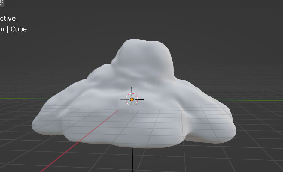
Once you have all the right modifiers save the blend file and then the end result for the geometry should look something like a cloud or you should start again haha heres my end result:
Select Verticies and Create a Vertex Group
Next we want to select the rim of verticies around the bottom of the cloud like so:
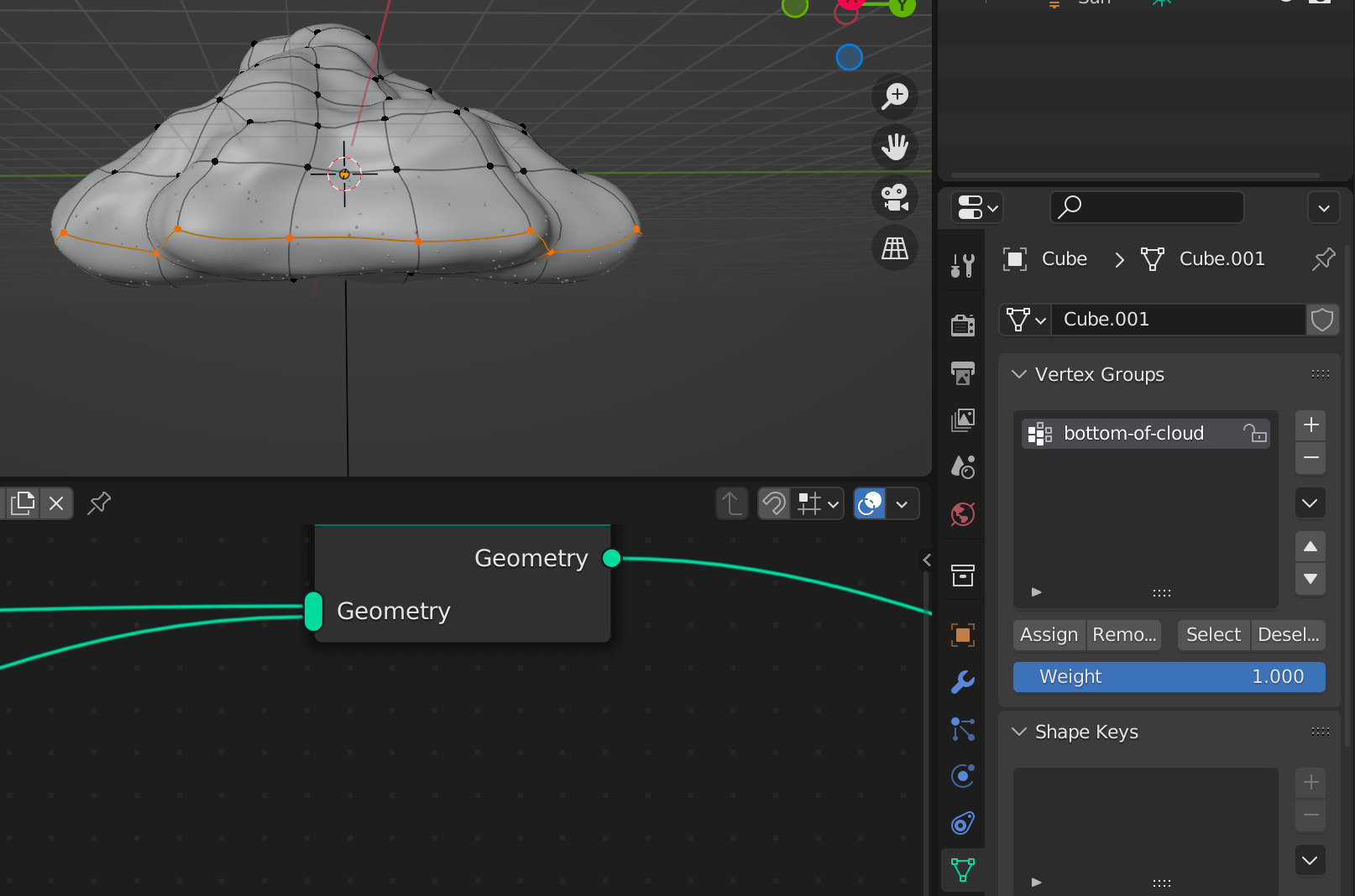
And then go to this tab (object data properties):

and add a vertex group and click assign while you have all your rim verticies selected.

This becomes important as we only want to apply the instances of the light shaft to the bottom of the cloud..
Otherwise it will look quite odd having the faux light coming out of the top of the cloud!
Create a Light Shaft on a 2D Plane
First of create a plane and scale it and go into edit mode and move the vertices.
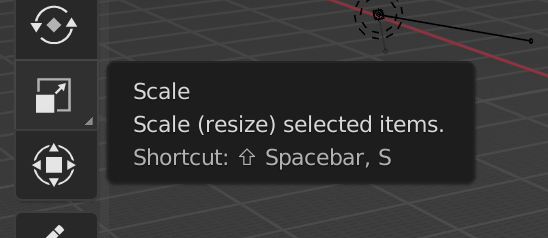
Scaling the plane by pressing this button on the left:
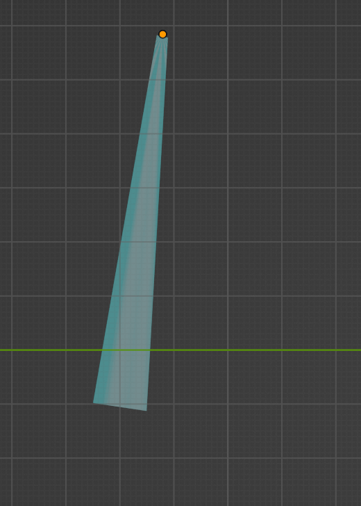
and then scaling into something like this:
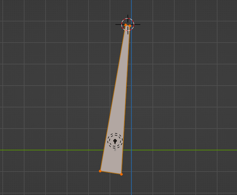
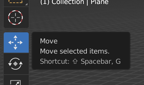
You can move individual verticies by going into edit mode clicking on a vertex and then translating it with clicking on this option:
Before we begin the shading part, I’ll show you what node setup I have in the shader tab with the plane selected:

So we have a basic principled BSDF shader, pretty standard at this point.
We essentially need radial gradient texture eminating from the origin and we will move the origin to the shorter top edge of the plane.
Start off by adding texture coordinates node and a gradient texture with radial selected and plug the output to a wave texture.
Next step is to press shift and right click to move the 3D cursor object to the top of the shorter end of the plane.
Click on object dropdown in layout tab —> set origin —> move origin to 3D cursor. At this point we should be good to progress.
Add a wave texture and plug the radial gradient to the wave texture. Then plug the wave texture into the BSDF node. So it should look something like this:
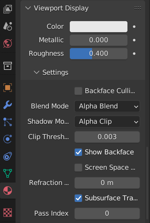
Before we add opacity we should change the blend mode in blender so when we do have opacity set lower it will actually show as more invisbile in the 3D view port.
So go to this material properties tab on the side and select blend alpha mode:
Once we have this add a color ramp and add 3 points to it.
To the left select the color to be what ever (I chose a blue) and set the opacity to something really low like 0.1 or lower. the middle point choose white or a light color and set the opacity slightly higher and the final furthest right point select white but put the opacity to 0. You node should look like this:
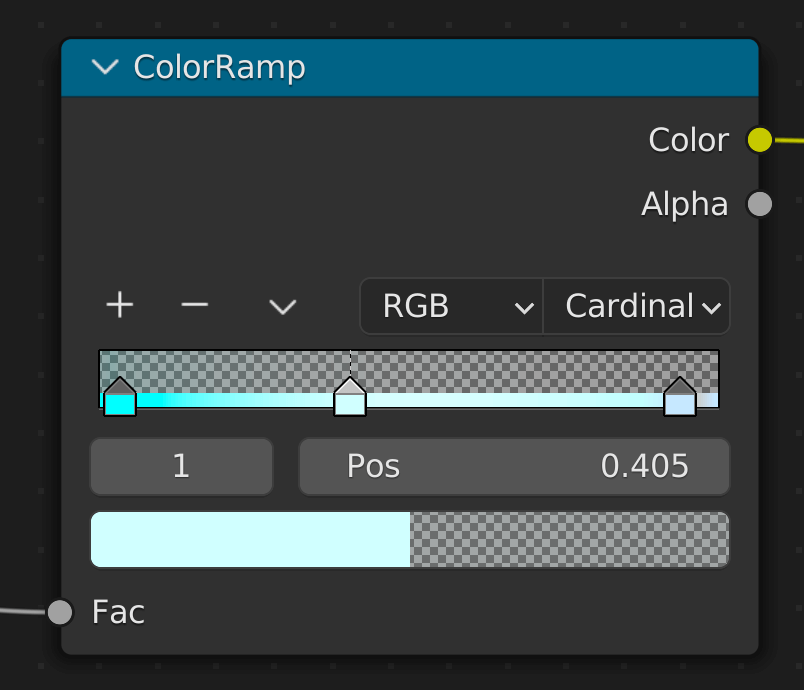
The color ramp has the input color from the wave texture and the output of the color ramp is put in the color and alpha with the principled BSDF.
Use Geometry Nodes to Scatter Points / Instances on the Bottom of the Cloud Vertex Group
Good old geometry nodes..
We are aiming to distribute points on that vertex group we created earlier and then subsequently we will need to put instances on these points, which will be the shaft plane we created earlier.
- distribute points (with vertex group selected on a geometry node)
N.B. Vertex groups show up on the evaluated data tab as an attribute to the geometry you have selected.
Here is the geometry node setup:
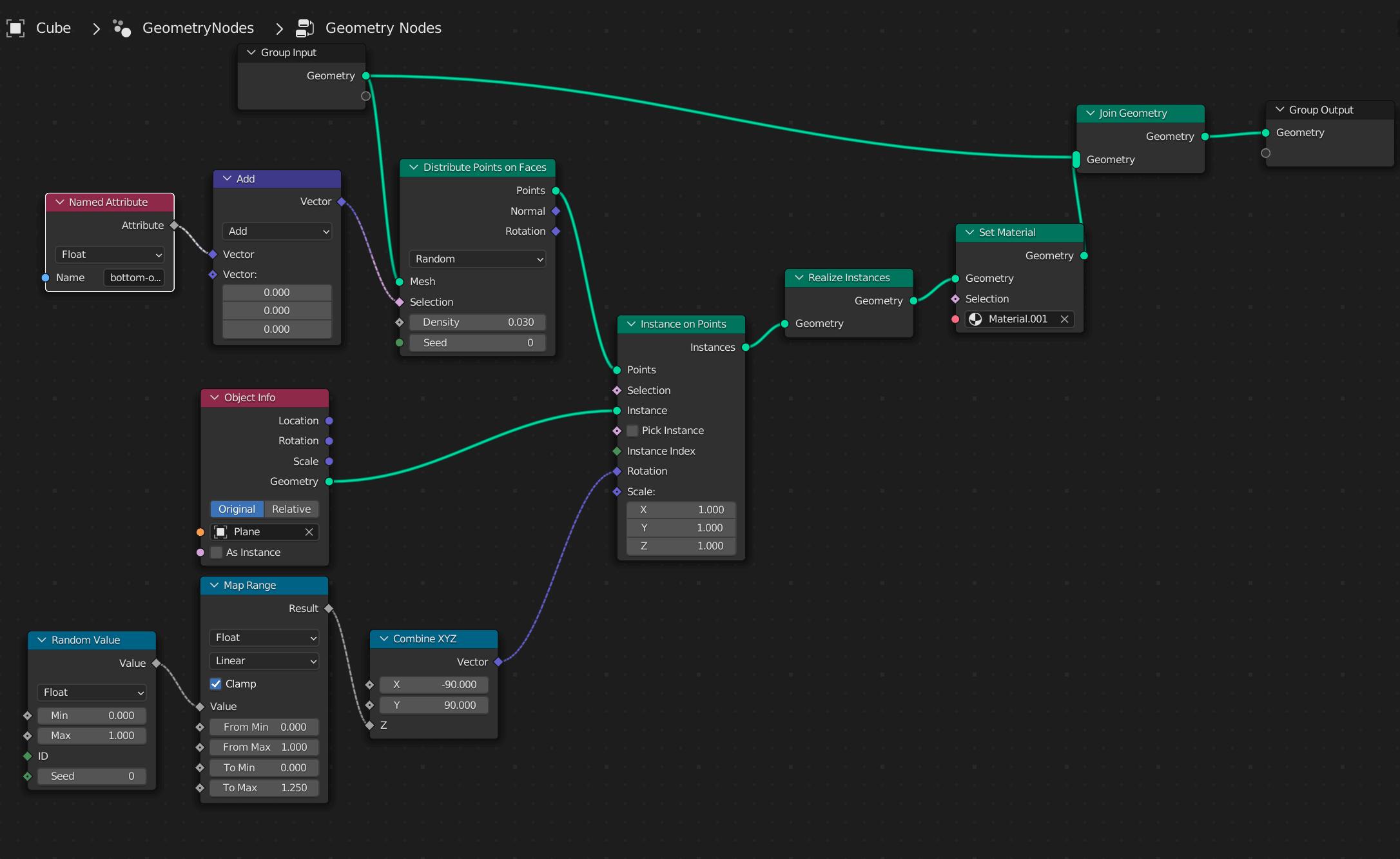
(we will fix the color and alpha of the light shafts when baking the intitial light shaft we instanced from.)
- instance on point node, to spread the instance using a named attribute as the selection, with the vertex group we just created before:
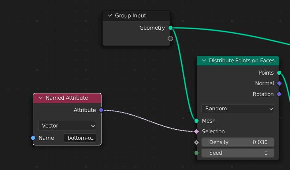
- select the instance
- use a combine XYZ node for the rotation of the instance
- vector node connected do:
- x = -90
- y = 90
- z = 0
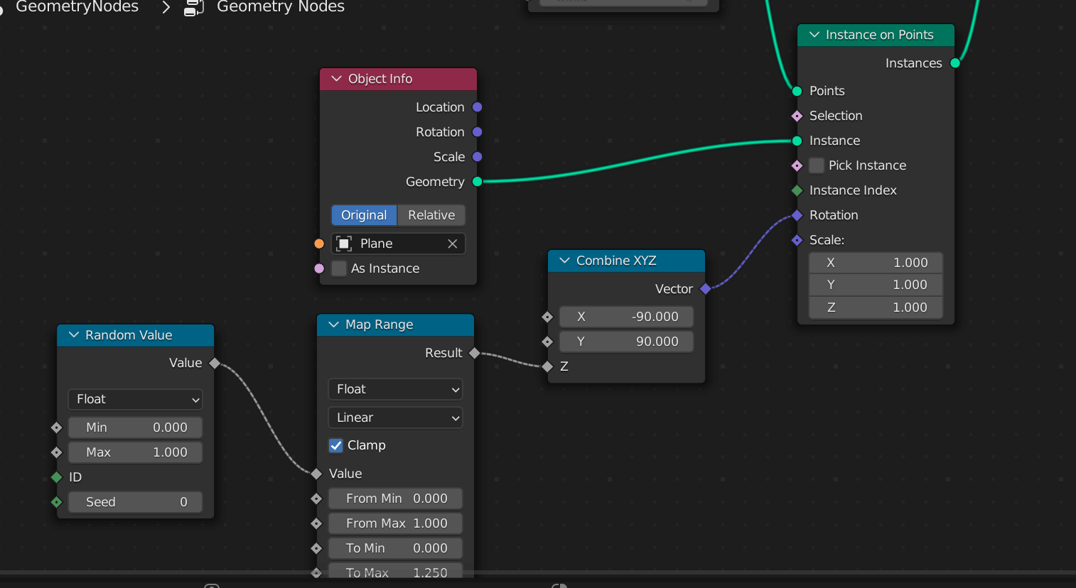
- for z rotation do this:
- otherwise when you get to a certain angle because we are instancing planes you wont see anything and it will look super fake
- so we are randomly rotating around the z axis as this gives a more realistic effect with the shafts so you can allways see something rather than at a point seeing nothing.
Bake Procedural Light Shaft Texture + Apply Geometry Nodes
Bake Procedural Light Shaft Texture
Baking is quite easy to be honest. There are some downsides to blender you cant bake opacity channel on its own, but you can bake opacity in the combined bake option. I will explain abit more soon.
First of go to the uv editing tab, go into edit mode with the initial plane selected press the a key. With the models verticies selected go to the unwrap in the uv dropdown and press it. Now we have a accurate uv map.. which we will need to map this texture to the geometry accurately.
Go to this tab and make sure you are in cycles (as this is the only place you can bake):

Add a image node in the shading tab with 1024x1024 texture in it with it not being connected to anything.
With the individual plane we created selected and the image node we just created…
Scroll down to the bake option in the panel we were just in and select combined option for baking and unselect transmission but do a combined bake, like so:
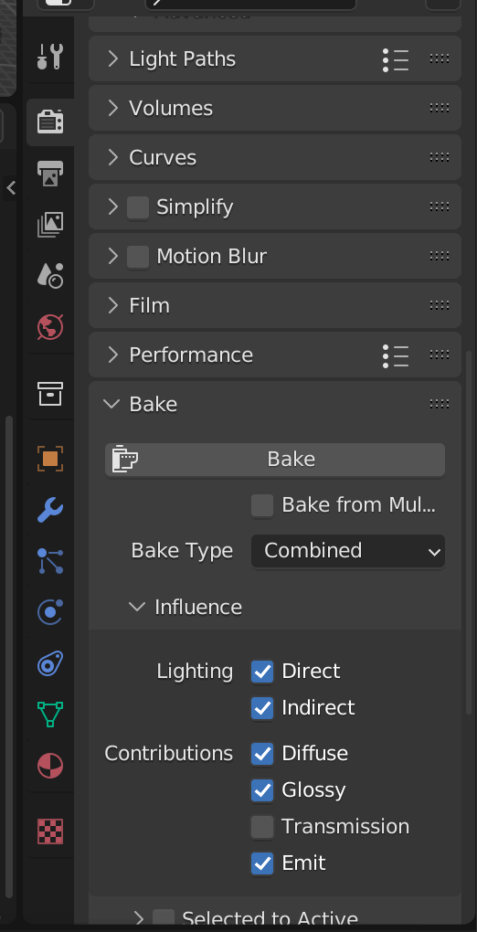
With all this done press the bake button and wait for it to bake.
Inspect the image editing tab and see if the bake has worked, with opacity being affected, mine looks like this:
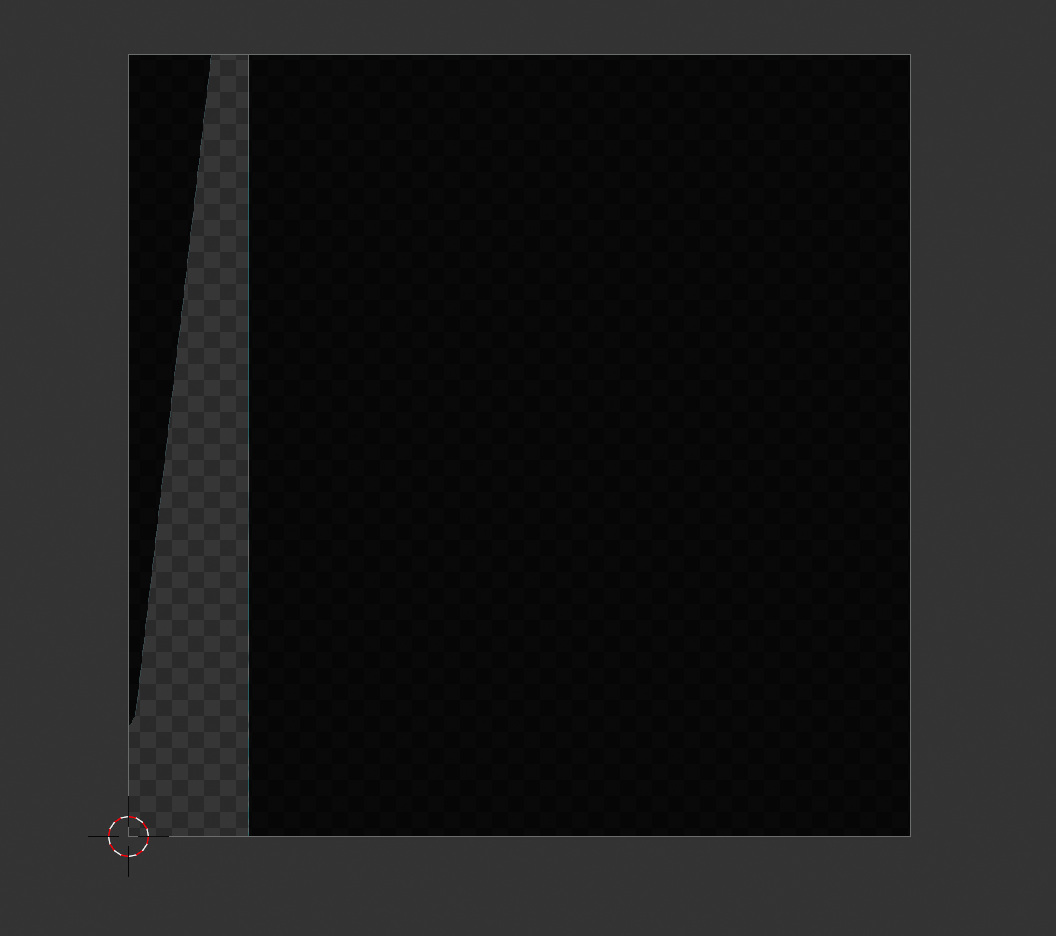
Apply Geometry Nodes
So one thing you may not be aware of is you can apply geometry nodes much like you would a normal modifier, go to the modify tab and press apply on the geometry nodes modifier:
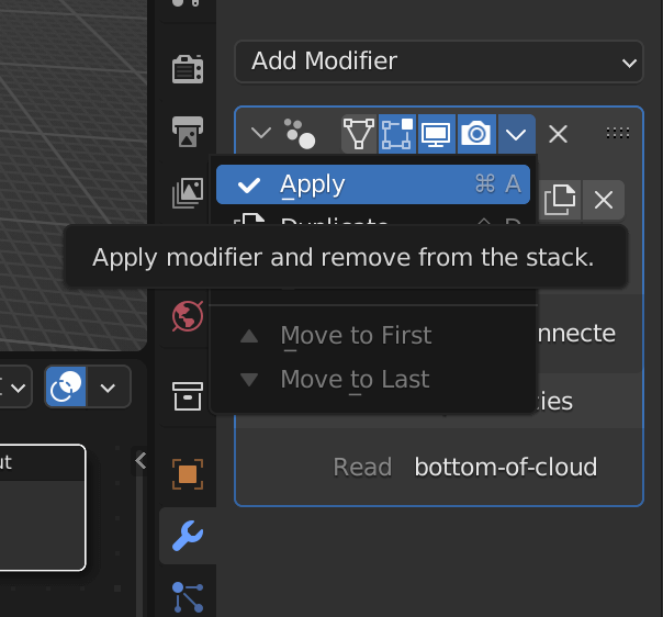
Now you should have a normal geometry which has been evaluated 🙂
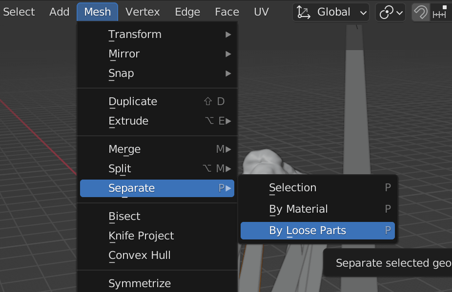
Now go to modeling tab at the top and select the joined geometry do:
Now in layout tab the key bit is yet to be done. We need to select all the loose planes and then select the very initial plane and do the following:
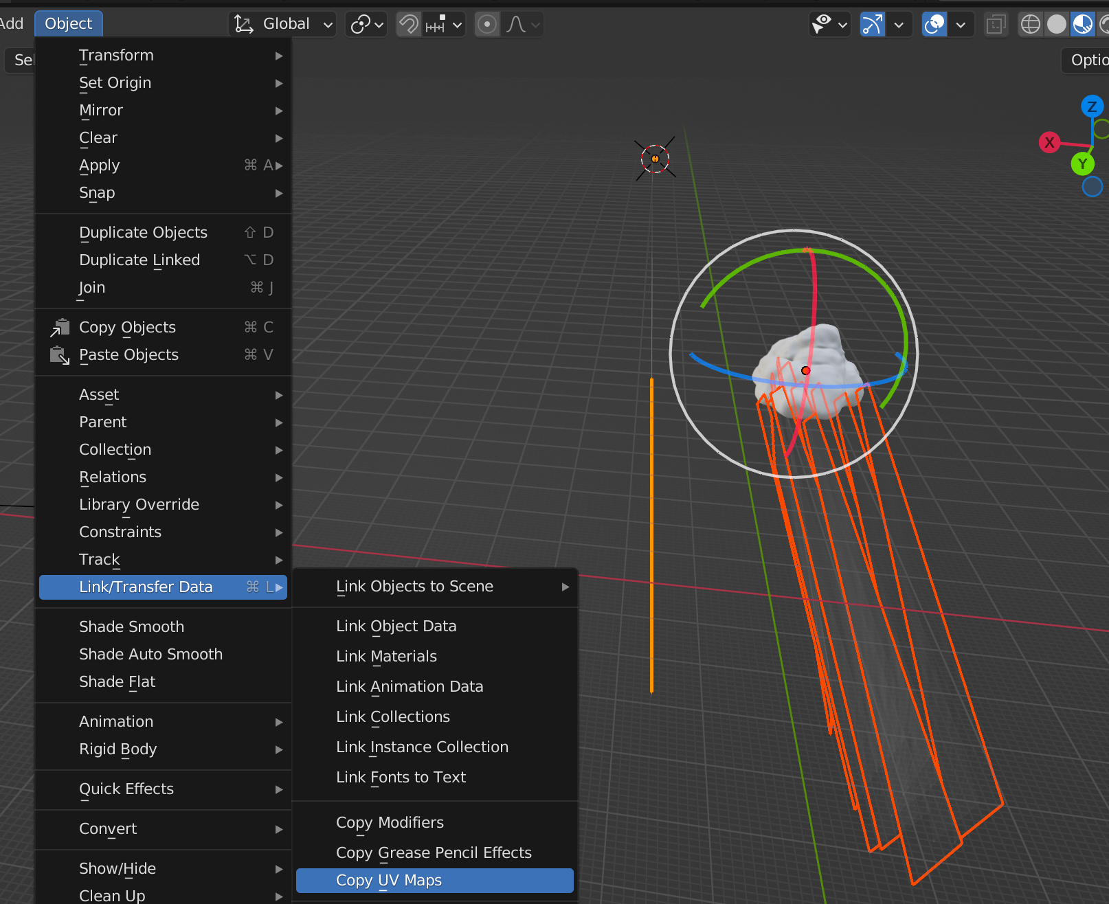
Look carefully we select the planes we created by applying the geometry nodes and then selected the initial plane with the UV map where we unwrapped (which is an orange color) and hit copy uv map. This ensures we can map our baked texture to each of the planes we generated. If you dont do this it will look odd and the colors and alphas will be all messed up.
Here is my latest blend file.
And here is the gltf file.
Final Thoughts:
This isnt quite perfect and would need some tweaking for production apps.
BUT is a nice alternative to the very intensive real time clouds, using fbm functions with multiple octaves or layers of noise functions.
And is probably better suited to a 3D web app in a environment which has a need for a bright day or night time scene..
Image the light shafts flickering and blooming with a custom fragment shader 👀
Any how until next time, have fun with it and try it out your self! 😄